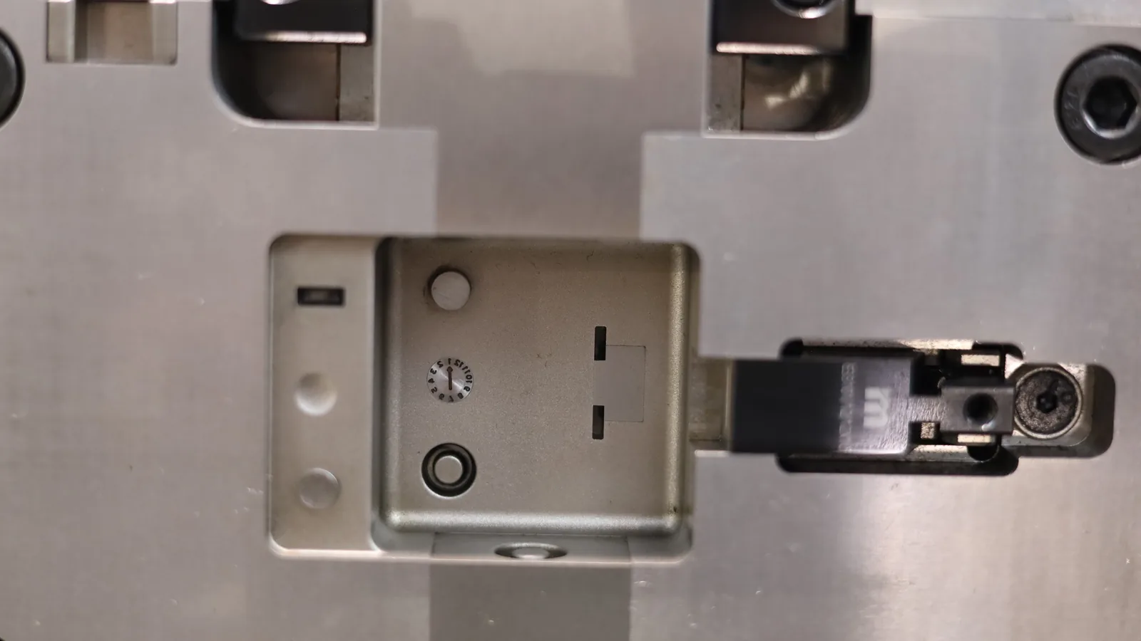
What matters
- Mating steel faces deserve the same attention as gates, lifters and slides: a shut-off that is not fitted properly becomes a flash source.
- Faces that seal sideways are not pressed together by clamp force. They need draft, support behind them and accurate fitting.
- Through-hole cores need interlocking support and a deliberate mismatch allowance, or the holes come out undersized and the edges flash.
What counts as a shut-off
Any two faces in a mold that come together when the mold closes, and shut off or divert the flow of plastic inside the cavity, is a shut-off, and the term covers more geometry than most part designers expect when they first sketch a hole in a wall. Four cases carry that name. A side-wall hole, a snapping hook, a louver stack and a family-tool runner all belong to the same conversation.
The most common case is a pad on the core that seals against the vertical wall of the cavity and forms a hole or window in that wall. That seal wears like any other. Once it does, plastic sneaks past the pad and the feature comes out with flash where a clean edge belonged, which is how most shut-off problems are first reported at the press.
A pass-through core is the second case: a standing block on one side of the tool mates into a pocket on the other side, so that one face of the block forms the inside of a hook or clip while the remaining faces, drafted for the purpose, seal against the walls of the pocket. No side action is needed. Hooks, clips and long through-holes can all be molded this way, which is a good reason to know the technique before a design is frozen.
Third comes the step or parting-line shut-off, where the sealing faces sit normal to the opening direction and the press closes them directly under clamp force, which makes the seal a question of fit and support. The fourth case is different. The same word also covers flow control: a shut-off that diverts or blocks melt flow rather than forming an edge is what a mechanically closed valve gate does in a hot-runner system.
| Shut-off | What forms it | How the seal is held |
|---|---|---|
| Pad against a wall | A core-side pad sealing against the cavity wall to form a hole or window | Steel stiffness and the fit of the faces, not clamp force |
| Pass-through core | A block mating into a pocket to form holes, hooks or clips | Steel stiffness, support at the far end, and interlock |
| Step or parting-line land | Faces normal to the opening direction | Clamp force, plus accurate fitting of the land |
| Flow shut-off | A mechanically closed valve gate, or a land that blocks flow to one cavity | Mechanical closure, not a face seal |
What holds a shut-off closed
Melt pressure pushes the cavity open, the clamping unit answers by pressing the two mold halves together, and that force is what seals every face lying normal to the opening direction, which is the case at the parting line. Parallel faces get nothing from it. The press holds the mold closed, and it does not squeeze two faces that run sideways to the closing direction.
The load path for a lateral shut-off runs through the tool instead, because melt pressure acting on the exposed face of a pad or block pushes it sideways, and stiffness, support and fit are the only things resisting that push, which is why a tall block standing on thin steel, with nothing behind it to stop it flexing, will let plastic past as soon as the process runs warm. Support decides the outcome. One question settles most design reviews: what stops this face from moving? A thin section of steel with nothing behind it will flash.
Flowing plastic adds a second load. The Covestro part and mold design guide describes how the advancing flow can exert very high side forces on tall cores forming deep or long holes, bending them out of position and, under severe conditions, fatiguing the steel until the core breaks. Interlocks change that. Cores that interlock into the opposite half resist deflection far better than cores which simply kiss off.
Fitting is what finally makes the seal, and mold builders normally leave a slight positive interference, or crush, on shut-off and parting-line surfaces so the steel burns in and closes the gap. Insert material can rule that out. The Copper Development Association's mold design guidelines note that press is avoided with copper alloy cores and inserts, because their higher ductility invites peening and hobbing at shut-offs and at the parting line.
Registration belongs in the same conversation, since a shift of the halves under injection pressure squeezes one shut-off tighter while its partner on the far side opens. Guide pins and taper locks control that movement. Their wear shows up first as flash on one side of the part, and the same guidelines describe alignment interlocks as mandatory where a tool uses vertical shut-offs or telescoping cores.
Draft, spotting and a seal you can maintain
A shut-off face does something a normal cavity wall never has to do: it slides past its partner on every mold close, touches it, and seals, which is why Protolabs sets the minimum draft for shut-off faces at 3 degrees. Clearance is the point. Less draft means steel scrapes on the way in, contact spots burnish unevenly, and the seal is gone within the first weeks of production.
More draft is not automatically safer, because the sealing land is what forms the edge of the hole and a steeper face narrows the land that carries the load, which is a compromise the toolmaker has to make deliberately. Draft the approach, hold the land. That land also wants to sit away from sharp corners, where a worn edge becomes visible on the part long before it affects function.
The seal is finished by hand at the bench, where spotting checks contact with marking compound or shim stock and the surfaces are adjusted until the pattern is even. Contact must be even. A high spot at one corner of a shut-off carries the whole load, peens, and then swallows plastic.
| Design choice | What it buys | What it costs |
|---|---|---|
| Drafted shut-off face, 3 degrees or more | Faces pass cleanly on close and burnish into a seal | The land narrows as it wears, and the part keeps a witness line |
| Butt or step land at the parting line | Simple machining, sealed directly by clamp force | Any loss of fit or support appears as flash at the step |
| Interlocked core ends | Flow cannot bend the core, so through-holes hold position and size | Extra fitting and maintenance on the shut-off faces |
| Replaceable or hardened insert at the wear face | Wear stays local and can be serviced without welding the cavity | More components, another fit-up, and spare parts to hold |
Through-holes: support, mismatch and hole size
A through-hole needs steel from both sides meeting in the middle, which is where shut-off design and core design become the same subject, and long cores are the weak point in that arrangement. Flowing plastic bends them. A bent core forms a hole in the wrong place, and the deeper the hole, the less the core resists the moving melt on its own.
Read the numbers below as a statement about support rather than about diameter, because a core held at one end is a cantilever. Held at both ends, it changes. The same core can then be twice as long for the same diameter, and the gain comes from the interlock rather than from stronger steel.
- Mismatch between mating cores is the second effect, and it is easy to miss because each half of the tool looks correct on its own while the pair forms an opening smaller than the drawing intends, which is why a shaft that should pass through cleanly will not, and why the problem rarely appears until the two halves are checked against each other.
- One core can be larger. Where the design allows it, sizing one core slightly larger carries the intended diameter through normal mismatch, and holes too tight to step that way may need interlocking features on the core ends, at extra construction and maintenance cost.
- For a hole that runs across a long part, a third option avoids a slide entirely: a segmented trough on each half creates a row of shut-offs that together form the through-hole, a pattern Protolabs illustrates for hinges, bolt holes and pivot pins. Witness marks come with it. The hole carries a joint line at every segment, so the method suits a fastener hole far better than a sealing or bearing surface.
- All of these choices move the tool price, since a hole formed by steel contact keeps the mold straight-pull while a hole that needs a slide adds a mechanism with its own travel, support, sensing and wear parts, which the undercuts guide works through in more detail.
| Core geometry | Typical length-to-diameter limit |
|---|---|
| Blind-hole core, unsupported | 3:1 |
| Blind-hole core, with flow symmetrical around it | up to 5:1 |
| Through-hole core, supported at both ends | typically 6:1 |
| Through-hole core, interlocked, symmetrical fill | up to 10:1 |
When a shut-off starts flashing
Flash is usually the first sign that a shut-off is no longer sealing, and it gets reported as a part defect long before anyone opens the mold, which the Covestro guide treats as a maintenance line item rather than a design failure. Tool condition matters here. Keep parting lines and mold kiss-off areas in good condition so flash does not have to be trimmed, and where flash is unavoidable, orient the parting line and kiss-off points so the thin fin lands on a non-cosmetic face that nobody inspects.
Some shut-off geometry is expensive to keep in condition, and the same guide warns that molds built with numerous angled kiss-offs of bypass cores are expensive to construct and maintain, as well as prone to damage and flash. Design can remove them. Where the part allows it, extending a vent slot over the top of a corner edge, or sloping the louver surface, takes the shut-off and the side action with it.
Wear is not spread evenly across a shut-off, concentrating where the land is narrowest, where the flow hits the face, and at the corners that take load first. Treat the faces accordingly. Harden the surface that wears, make the wearing part replaceable, and keep the alignment hardware in condition, because steel selection and surface treatment decide how long the first two of those last.
Not every flash event is wear: a shut-off that flashes on the first sample is a fitting or support problem, while one that starts flashing after a few hundred thousand cycles is wear and needs a repair. Repair first, then process. A tool that flashes only at high hold pressure, or only on one press, is usually a clamp and process question, and checking tonnage, melt temperature and hold pressure is cheaper than pulling the mold.
What to send with an RFQ
A toolmaker prices shut-offs against the decisions a design leaves open, and six answers do most of the work.
- Which openings must be sealed by steel contact, and which can move to the parting line instead.
- Whether the hole may carry a witness line or a step, and which face is cosmetic.
- The hole tolerances that matter, because core mismatch changes the opening.
- Whether segmented shut-offs are acceptable on a long through-hole, in place of a slide.
- Resin, filler content and expected volume, since all three set how fast the faces wear.
- Which surfaces may be hardened or made replaceable, and who pays for the first rebuild.
Set the assumptions, then read the range
The molding cost estimator behind /quote reads part geometry and returns a first-pass range for tool and part cost, with its assumptions listed, so model the shut-off the way you intend to mold it: straight-pull. The estimate follows that choice. Treat a printed range as a budget for planning rather than a supplier's quotation, and expect a toolmaker to confirm the design points above before any price becomes firm.
Use this as a design review, not a production release
These guides support early planning. The selected resin supplier, toolmaker, and molder still need to confirm the final geometry, process window, tolerances, safety factors, validation plan, and commercial assumptions for your application.